Implement a 2X1 Mux using Gate-level Modeling. Simulate in either ModelSim or Xilinx ISE. Submit the code and wave files.
Main Module :
module mux2 (out, i0, i1,s0);
output out;
input i0,i1,s0;
wire s0n,y0,y1;
and a0 (y0,i0,s0);
and a1 (y1,i1,s0n);
not n0 (s0n,s0);
not n1 (s1n,s1);
or r (out,y0,y1);
endmodule
Stimulus :
module stimulus;
wire out;
reg i0,i1,s0;
mux2 mux2_1 (out,i0,i1,s0);
initial
begin
s0=0; i0=0; i1=0;
#10 s0=0; i0=0; i1=1;
#10 s0=0; i0=1; i1=0;
#10 s0=0; i0=1; i1=1;
#10 s0=1; i0=0; i1=0;
#10 s0=1; i0=0; i1=1;
#10 s0=1; i0=1; i1=0;
#10 s0=1; i0=1; i1=1;
#10 $stop;
#10 $finish;
end
endmodule
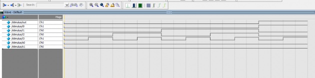
Waveform:
Observation : From above waveform, we observe that the output is according to below given truth table:
|
S0 |
I0 |
I1 |
out |
|
0 |
0 |
0 |
0 |
|
0 |
0 |
1 |
1 |
|
0 |
1 |
0 |
0 |
|
0 |
1 |
1 |
1 |
|
1 |
0 |
0 |
0 |
|
1 |
0 |
1 |
0 |
|
1 |
1 |
0 |
1 |
|
1 |
1 |
1 |
1 |
Task#2 :
Implement a 4X1 Multiplexer in Verilog using Gate-level modeling. Also simulate your design for verification (Create a proper Stimulus or Test Bench file).
Main Module:
module mux41 (out, i0, i1, i2, i3, s1, s0);
output out;
input i0,i1,i2,i3,s0,s1;
wire s0n,s1n,y0,y1,y2,y3;
and a0 (y0,i0,s1n,s0n);
and a1 (y1,i1,s1n,s0);
and a2 (y2,i2,s1,s0n);
and a3 (y3,i3,s1,s0);
not n0 (s0n,s0);
not n1 (s1n,s1);
or r (out,y0,y1,y2,y3);
endmodule
Stimulus:
module stimulus;
wire out;
reg i0,i1,i2,i3,s0,s1;
mux41 mux4_1 (out,i0,i1,i2,i3,s0,s1);
initial
begin
s0=0; s1=0; i0=0; i1=0; i2=0; i3=0;
#10 s0=0; s1=0; i0=0; i1=0; i2=0; i3=1;
#10 s0=0; s1=0; i0=0; i1=0; i2=1; i3=0;
#10 s0=0; s1=0; i0=0; i1=0; i2=1; i3=1;
#10 s0=0; s1=0; i0=0; i1=1; i2=0; i3=0;
#10 s0=0; s1=0; i0=0; i1=1; i2=0; i3=1;
#10 s0=0; s1=0; i0=0; i1=1; i2=1; i3=0;
#10 s0=0; s1=0; i0=0; i1=1; i2=1; i3=1;
#10 s0=0; s1=0; i0=1; i1=0; i2=0; i3=0;
#10 s0=0; s1=0; i0=1; i1=0; i2=0; i3=1;
#10 $stop;
#10 $finish;
end
endmodule
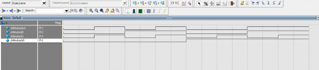
Waveform: