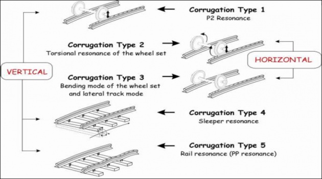
Causes of Corrugation
Humidity, especially in long tunnels or in tunnels near or under the water.
• High speeds trains, especially at electrified sections.
• Slipping of loco wheels, because of accelerating and braking actions especially at steep gradients and in case of emergency.
• Presence of rigid track, soft ballast and yielding formations.
• Non-uniformity of diameter of loco wheels and coning.
• Use of light railway wagons and coaches.
• Use of rails having high tensile strength i.e. composition of steel etc
Corrosion of Rails
Platform lines where trains make prolonged halts.
• Sidings where saline or corrosive goods are dealt with.
• Where rails are affected by the droppings of engine ashes such as at ash pits.
• Near water columns due to insufficient drainage.
• Tunnels and damp side-cuttings.
• Areas near the seacoast.
• Industrial belts.
• Steel alloys are used to reduce corrosion, coating with non-corrosive material
Hogging of Rails
A hogged rail is one with its end or ends bent downward in vertical plane. A hogged rail-end in the track is ascertained / measured by un-fishing the joints, removing the fastening and then measuring the extent of hog at the rail end by placing 1 meter long straight edge of a bar over the rail table, centrally over the joints to rectify the defects.
Defects Rectification: (i) cropping (ii) de-hogging (iii) welding and (iv) replacing 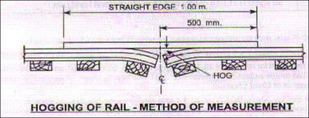
Strain and Restraint in a Rail
Movement of the rail due to temperature variations continues until sum of all the restraints provided by: Rail Fastening + Sleeper + Ballast, equals to Expanding or Contracting Force.
With ordinary and conventional Restraints, Restraining Force is expressed as the following relationship:
P = EA
Where P is the Restraining Force in a rail length per degree change in temperature.
E is Modulus of Elasticity of rail’s steel and it is equal to 2 x 10⁶ kgf / cm2.
A is the Area of Cross-Section of rail which is usually 66.15 cm2 for 52 kg-rail i.e. 52 kg / m.
is the Coefficient of Linear Expansion of Rail’s Steel which is usually 1.2 x 10⁻⁵ / Co.
Now calculating P
P = (2 x 106) x (66.15) x (1.2 x 10-5) =
1587.6 kgf / Co = 1587.6/1000 = 1.588 t / Co
Buckling of Rails
Track goes out of alignment especially at curves where expansion is prevented either because of insufficient expansion gap or excessive tightness of the joints.
Remedies Against Buckling
Joints should not be tightly jointed to the extent which may prevent expansion and contraction of the rails.
Number of welded rails should not be too large.
Sufficient expansion gap should be provided.
Contact surfaces between rails and fishplates should be lubricated.
If welded rails are to be used, then either steel sleepers should be provided or rails should be properly anchored to the sleepers. 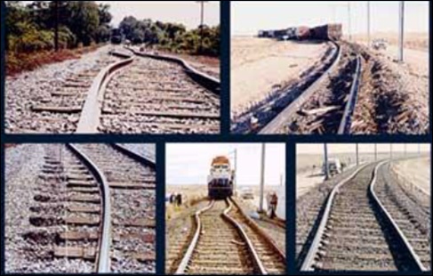
Failure of Rail
Crushed Head: Weak end support because of loose fish plate.
Split Head: It is a manufacturing defect and when crack is opened; it is smooth and dark in colour.
Flow of Metal in Heads: The metal is forced out and the head gets widened, usually producing the Burrs.
Split Web: It is initiated from the strained bolt-hole.
Horizontal Crack: When the worn fish-plates are used or ballast is not properly packed.
Horizontal Fissure: It is caused due to defective rail head.
Transverse Fissure: This is a manufacturing defect; it has a round or oval bright spot. It is very dangerous as the rail breaks before the defect becomes visible.
Square or Angular Breakage: Sometimes rail breaks through the vertical plane (like slicing), that is known as square or angular breakage. 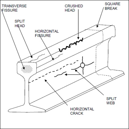
Rail Creep
Longitudinal movement of rails in a track in the direction of motion is called Rail Creep. It varies from a negligible length to a few centimeters. The rail may either move with respect to sleepers or sleepers may move along with rails due to Rail Creep.
Three Theories related to Rail Creep
Drag Theory: According to this theory, the rails are pushed backwards by the Driving Wheel of locomotive. Whereas other wheels (Idle-Wheels) of the locomotive and wagons push the rails in the direction of motion. As a result of this, creep takes place in the direction of motion.
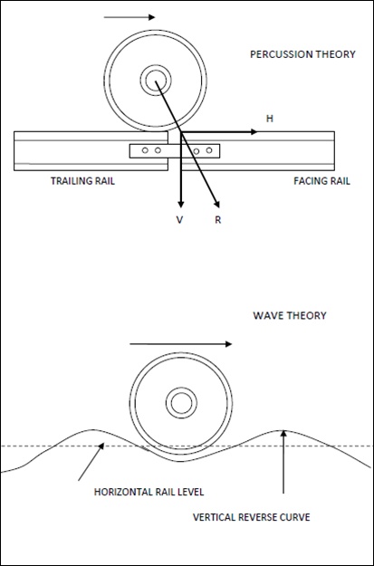
Wave Theory: As the rail gets depressed under the rolling wheel, a vertical reverse curve is formed. The wheels have a tendency to push the rail in the direction of train. With the successive forward motion of the wheel, creep is carried forward along the length of rail.
Percussion Theory: Rail-end ahead of the joint gets battered. Impact of the train-wheel tends to push the rail forward giving rise to creep. When the wheel crosses over the joint, force acts normal to the contact surface. It's horizontal component causes the creep, whereas the vertical component causes the battering i.e. percussion of the rail-end. 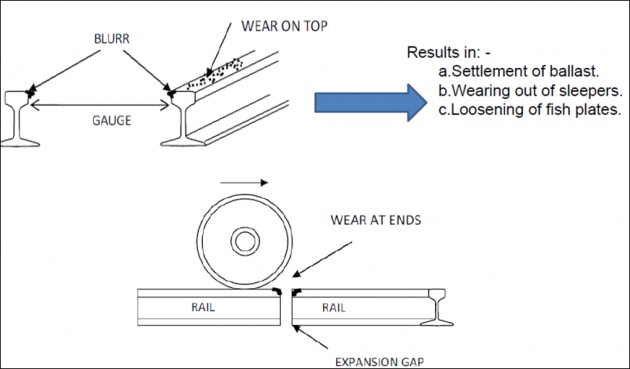
Fixing the Creep
Pulling the Rails Back-Method:
Provision of Creep Anchors:
Creep anchors must be strong to resist the induced stresses.
Number of anchors depends upon the expected intensity of creep.
Placed at originating points; not where the creep is produced.
Not placed on bridges. Extra anchors are provided off-the-bridge, on either sides.
Additional creep-anchors to be placed on railway stations and level crossings.
Defective creep anchors should be replaced when observed to prevent the wearing of those anchors and accumulation of increased creep in the rails. 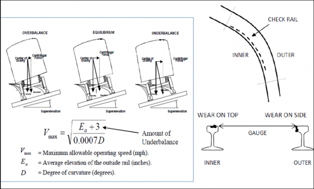

Conning of Wheels & Tilting of Rails
Disadvantages:
More tendency to wear at inner edges.
Gauge tends to widen out.
If no base plates are provided, sleepers under the outer edge get damaged.
Remedy: To reduce the damaging effects, rails are tilted inwards with 1:20 slope. Sleepers are cut inwards to receive the tilt of rails, and this is called ‘Adzing' of the wooden sleepers. The advantages are: -
Gauge remains maintained.
Wear of rail head is reduced.
Increased life of sleepers and rails. 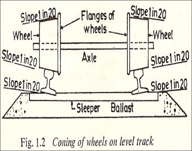
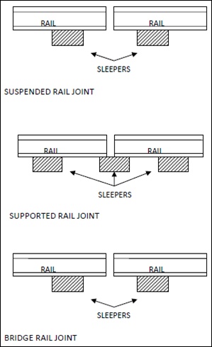
Rail Joints
Suspended Joints: More commonly used joint where the rail ends are jointed sufficiently away from the rail-end.
Supported Joints: Rail ends rest exactly on the centre of a supporting sleeper. Appears having good support but not so good; not good for heavy loads. If hardly supported, performance not so good and joint has a tendency to become a Tight-joint.
Bridged Joints: In this type of joint, sleepers do not work as unyielding fixed supports. Construction is similar to suspended joints except the length of the metal (usually a rail-clip) is used to connect the ends of two rails so that the joint acts partly suspended and partly supported. To adjust these metal plates, wooden sleepers are notched.
Welding of Rails
Purpose:
• To reduce the number of joints and thus affecting the saving in maintenance cost.
• To restore the worn out and damaged rail section.
• To repair the worn out or damaged points and rails mostly along the curves.
• To restore the corroded sections of the head of rails or to repair any similar defect.
Advantages:
• Less number of joints resulting in reduction of construction and maintenance cost of the joints.
• Increase in life of the rails due to reduction in wear at the rail end.
• Increase in travelling comfort of the train / passengers due to reduction in joints.
• Reduction in creep.
• Increase in load bearing capacity of the track.
• Saving in fuel due to reduction in traction effort and resistance.
• Reduction in sabotage in train-travel.
• Increase in stability and strength of track.
Methods:
• Flash Butt Technology
• Chemical (Thermit) Welding method