Task#01:
Implement a 4X16 decoder using instantiation (use two 3X8 decoders).Simulate in either Xilinx ISE or Modelsim.Submit the code and the wave file…..
Module:
module decoder16 (d1,d2,x,y,z,w);
output [15:8]d1;
output [7:0]d2;
input x,y,z,w;
assign e=~w;
decoder8 dcdr1 (d1,x,y,z,e);
decoder8 dcdr2 (d2,x,y,z,w);
endmodule
module decoder8(u,x,y,z,e0);
output [7:0]u;
input x,y,z,e0;
assign u[0]=~x&~y&~z&e0;
assign u[1]=~x&~y&z&e0;
assign u[2]=~x&y&~z&e0;
assign u[3]=~x&y&z&e0;
assign u[4]=x&~y&~z&e0;
assign u[5]=x&~y&z&e0;
assign u[6]=x&y&~z&e0;
assign u[7]=x&y&z&e0;
endmodule
Stimulus:
module stimulus;
wire [15:8]d1;
wire [7:0]d2;
reg x,y,z,w;
decoder16 dcdr16 (d1,d2,x,y,z,w);
initial
begin
w=1;x=0;y=0;z=0;
#10 w=1;x=0;y=0;z=1;
#10 w=1;x=0;y=1;z=0;
#10 w=1;x=0;y=1;z=1;
#10 w=1;x=1;y=0;z=0;
#10 w=1;x=1;y=0;z=1;
#10 w=1;x=1;y=1;z=0;
#10 w=1;x=1;y=1;z=1;
#10 w=0;x=0;y=0;z=0;
#10 w=0;x=0;y=0;z=1;
#10 w=0;x=0;y=1;z=0;
#10 w=0;x=0;y=1;z=1;
#10 w=0;x=1;y=0;z=0;
#10 w=0;x=1;y=0;z=1;
#10 w=0;x=1;y=1;z=0;
#10 w=0;x=1;y=1;z=1;
#10 $stop;
#10 $finish;
end
endmodule
Observations:
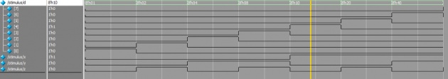
From the output we can see that 4X16 decoder is selecting a line according to the input pattern. Only one of the 16 outputs are high at any given time. The output that is high is selected by the 4 bit input word.
We can write a truth table that shows all the combinations of inputs and outputs:
w,x,y,z output
0,0,0,0 d2[0]
0,0,0,1 d2[1]
0,0,1,0 d2[2]
0,0,1,1 d2[3]
0,1,0,0 d2[4]
0,1,0,1 d2[5]
0,1,1,0 d2[6]
0,1,1,1 d2[7]
1,0,0,0 d1[8]
1,0,0,1 d1[9]
1,0,1,0 d1[10]
1,0,1,1 d1[11]
1,1,0,0 d1[12]
1,1,0,1 d1[13]
1,1,1,0 d1[14]
1,1,1,1 d1[15]
Task#02:
Module:
module decoder (d,x,y,z);
output [7:0] d;
input x,y,z;
assign d[0] =~x & ~y& ~z;
assign d[1] =~x&~y&z;
assign d[2] =~x&y&~z;
assign d[3] =~x&y&z;
assign d[4] =x&~y&~z;
assign d[5] =x&~y&z;
assign d[6] =x&y&~z;
assign d[7] =x&y&z;
endmodule
Stimulus:
module stimulus;
wire [7:0]d;
reg x,y,z;
decoder dcder (d,x,y,z);
initial
begin
x=0;y=0;z=0;
#10 x=0;y=0;z=1;
#10 x=0;y=1;z=0;
#10 x=0;y=1;z=1;
#10 x=1;y=0;z=0;
#10 x=1;y=0;z=1;
#10 x=1;y=1;z=0;
#10 x=1;y=1;z=1;
#10 $stop;
#10 $finish;
end
endmodule
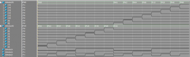
Wave File: