Objectives:
To program and use the TWI feature of AVR
To transmit a character from Master and receive at Slave ATmega16 microcontrollers
using TWI feature of AVR
Introduction:
The Two Wire Interface (TWI) protocol allows the systems designer to interconnect up to 128
different devices using only two bi-directional bus lines, one for clock (SCL) and one for data
(SDA). An external pull-up resistor is required to be connected for both the TWI pins to keep the
line in high state when these are not driven by any TWI device. All devices connected to the bus
have individual addresses. In TWI protocol, there are built-in mechanisms to resolve the issues
of bus contention. The ATmega16 TWI includes the following features:
Simple, powerful and flexible communication interface with only two bus lines
Master and Slave operation supported
Device can operate as transmitter and receiver
7-bit address space allows 128 different slave addresses
Multi-master arbitration support
Up to 400 kHz data transfer speed
Fully programmable slave address with general call support
Address recognition causes Wake-up when AVR is in Sleep Mode
Following figure show the interconnection of different devices connected to Serial Data (SDA)
and Serial Clock (SCL) pins. If none of device is driving the lines, pull-up resistors will keep the
lines at Vcc potential.
Following figure shows the condition for a valid data:
START and STOP conditions:
The Master initiates and terminates a data transmission. The transmission is initiated when the
Master issues a START condition on the bus, and it is terminated when the Master issues a
STOP condition. Between a START and a STOP condition, the bus is considered busy, and no
other Master should try to seize control of the bus.
A special case occurs when a new START condition is issued between a START and STOP
condition. This is referred to as a REPEATED START condition, and is used when the Master
wishes to initiate a new transfer without releasing control of the bus. After a REPEATED
START, the bus is considered busy until the next STOP.
As depicted below, START and STOP conditions are signaled by changing the level of the SDA
line when the SCL line is high.
Address Packet Format:
All address packets transmitted on the TWI bus are nine bits long, consisting of seven address
bits, one READ/WRITE control bit and an acknowledge bit. If the READ/WRITE bit is set, a read
operation is to be performed; otherwise a write operation should be performed. When a Slave
recognizes that it is being addressed, it should acknowledge by pulling SDA low in the ninth
SCL (ACK) cycle. If the addressed Slave is busy, or for some other reason cannot service the
Master’s request, the SDA line should be left high in the ACK clock cycle. The Master can then
transmit a STOP condition, or a REPEATED START condition to initiate a new transmission.
The MSB of the address byte is transmitted first. Slave addresses can freely be allocated by the
designer, but the address 0000 000 is reserved for a general call.
Data Packet Format:
All data packets transmitted on the TWI bus are nine bits long, consisting of one data byte and
an acknowledge bit. During a data transfer, the Master generates the clock and the START andSTOP conditions, while the receiver is responsible for acknowledging the reception. An
Acknowledge (ACK) is signaled by the receiver pulling the SDA line low during the ninth SCL
cycle. If the receiver leaves the SDA line high, a NACK is signaled. When the receiver has
received the last byte, or for some reason cannot receive any more bytes, it should inform the
transmitter by sending a NACK after the final byte.
Block Diagram of TWI Module:
TWI Registers:
As shown in the above block diagram, TWI module of AVR has following registers:
TWDR TWI Data register
TWAR TWI Slave address register
TWBR TWI Bit Rate register
TWSR TWI Status register
TWCR TWI Control register
In receive mode, TWDR will have received byte and in transmit mode, TWDR will have byte to
be transmitted.
TWAR contains the 7-bit slave address to which TWI will respond when working as slave. LSB
(Bit 0) of TWAR is TWGCE. Setting this bit enables the recognition of general call.
TWBR selects the division factor to control the SCL clock frequency while working in Master
mode. SCL frequency can be calculated from following formula:
SCL= CPU Clock Freg
16 + 2(TWBR) x4^TWRP
Where, TWBR holds the 8-bit value for a required SCL frequency. TWPS are two bits for
prescaler in TWSR register.
Bit # 7 6 5 4 3 2 1 0
Bit Name TWS7 TWS6 TWS5 TWS4 TWS3 - TWPS1 TWPS0
TWS7:3 TWS: TWI Status: These five bits show the status of TWI control and bus. For
more details, see datasheet
TWPS1:0 TWI Prescaler Bits:
0 0 1
0 1 4
1 0 16
1 1 64
TWSR (TWI Status Register)
Bit # 7 6 5 4 3 2 1 0
Bit Name TWINT TWEA TWSTA TWSTO TWWC TWEN - TWIE
TWINT This bit is set by hardware when the TWI has finished its current job and expects
application software response. If the I-bit in SREG and TWIE in TWCR are set, the
MCU will jump to the TWI Interrupt Vector. While the TWINT Flag is set, the SCL low
period is stretched. The TWINT Flag must be cleared by software by writing a logic
one to it. Note that this flag is not automatically cleared by hardware when executing
the interrupt routine. Also note that clearing this flag starts the operation of the TWI, so
all accesses to the TWI Address Register (TWAR), TWI Status Register (TWSR), and
TWI Data Register (TWDR) must be complete before clearing this flag.
TWEA The TWEA bit controls the generation of the acknowledge pulse. If the TWEA bit is
written to one, the ACK pulse is generated on the TWI bus if the following conditions
are met:
1. The device’s own Slave address has been received.
2. A general call has been received, while the TWGCE bit in the TWAR is set.
3. A data byte has been received in Master Receiver or Slave Receiver mode.
By writing the TWEA bit to zero, the device can be virtually disconnected from the
Two-wire Serial Bus temporarily. Address recognition can then be resumed by writing
the TWEA bit to one again.
TWSTA The application writes the TWSTA bit to one when it desires to become a Master on
the Two-wire Serial Bus. The TWI hardware checks if the bus is available, and
generates a START condition on the bus if it is free. However, if the bus is not free,
the TWI waits until a STOP condition is detected, and then generates a new START
condition to claim the bus Master status. TWSTA must be cleared by software when
the START condition has been transmitted.
TWSTO Writing the TWSTO bit to one in Master mode will generate a STOP condition on the
Two-wire Serial Bus. When the STOP condition is executed on the bus, the TWSTO
bit is cleared automatically. In Slave mode, setting the TWSTO bit can be used to
recover from an error condition. This will not generate a STOP condition, but the TWI
returns to a well-defined unaddressed Slave mode and releases the SCL and SDA
lines to a high impedance state.
TWWC The Write collusion bit is set when attempting to write to the TWI Data Register TWDR
when TWINT is low. This flag is cleared by writing the TWDR Register when TWINT is
high.
TWEN The TWEN bit enables TWI operation and activates the TWI interface. When TWEN is
written to one, the TWI takes control over the I/O pins connected to the SCL and SDA
pins, enabling the slew-rate limiters and spike filters. If this bit is written to zero, the
TWI is switched off and all TWI transmissions are terminated, regardless of any
ongoing operation.
TWIE When this bit is written to one, and the I-bit in SREG is set, the TWI interrupt request
will be activated for as long as the TWINT Flag is high.
TWCR (TWI Control Register)
C Code for data transfer between two ATmega16 using TWI feature of AVR:
/*
This program transmits a character from Master ATmega16 microcontroller and receives
the same on Slave microcontroller. TWI feature of ATmega16 is used to complete the
task.
*/
///////////////// CODE FOR MASTER/////////////////
#include<avr/io.h>
/////////////// Macros Definition/////////////////
#define Bit(x) (0x01 << (x))
#define BitGet(p, m) ((p) & (m))
#define BitSet(p, m) ((p) |= (m))
#define BitClr(p, m) ((p) &= ~(m))
void i2c_init(void)
{
TWSR = 0x00; //Use zero prescaler
TWBR = 123; //for SCL Freq = 1kHz and Fosc = 1MHz
TWCR = 0x04; //Enable TWEN, TWI Module
}
void i2c_start(void)
{
BitSet(TWCR, Bit(7)); //Clear TWINT, TWI Interrupt Flag
BitSet(TWCR, Bit(5)); //Enable TWSTA, TWI Start Condition
BitSet(TWCR, Bit(2)); //Enable TWEN, TWI Module Enable
while(!(BitGet(TWCR, Bit(7)))); //Stay till start condition transmitted
}
void i2c_write(unsigned char x)
{
TWDR = x; //Place date to be transmitted in TWI Data reg
BitSet(TWCR, Bit(7)); //Clear TWEN, TWI Interrupt Flag
BitSet(TWCR, Bit(2)); //Enable TWEN, TWI Module Enable
while(!(BitGet(TWCR, Bit(7)))); //Stay till data transmitted
}
void i2c_stop(void)
{
BitSet(TWCR, Bit(7)); //Clear TWINT, TWI Interrupt Flag
BitSet(TWCR, Bit(4)); //Enable TWSTA, TWI Stop Condition
BitSet(TWCR, Bit(2)); //Enable TWEN, TWI Module Enable
while(!(BitGet(TWCR, Bit(7)))); //Stay till stop condition transmitted
}
void main(void)
{
i2c_init(); //initialize TWI module
i2c_start(); //transmit start condition
i2c_write(0b01010101); //call the address of slave 0x55
i2c_write('A'); //Transmit ASCII of character A
i2c_stop(); //Transmit start condition
while(1);
}
///////////////// CODE FOR SLAVE/////////////////
#include<avr/io.h>
/////////////// Macros Definition/////////////////
#define Bit(x) (0x01 << (x))
#define BitGet(p, m) ((p) & (m))
#define BitSet(p, m) ((p) |= (m))
#define BitClr(p, m) ((p) &= ~(m))
void i2c_InitSlave(void)
{
TWCR = 0x04; //Enable TWEN, TWI Module
TWAR = 0b01010101; //Set Slave address
BitSet(TWCR, Bit(7)); //Clear TWINT, TWI Interrupt Flag
BitSet(TWCR, Bit(6)); //Enable TWEA, Send Acknowledge
BitSet(TWCR, Bit(2)); //Enable TWEN, TWI Module Enable
}
void i2c_listen(void)
{
while(!(BitGet(TWCR, Bit(7)))); //Stay till data transmitted
}
unsigned char i2c_receive(unsigned char ChkLast)
{
if(!ChkLast) //Place date to be transmitted in TWI Data reg
{
BitSet(TWCR, Bit(7)); //Clear TWINT, TWI Interrupt Flag
BitSet(TWCR, Bit(6)); //Enable TWEA, Send Acknowledge
BitSet(TWCR, Bit(2)); //Enable TWEN, TWI Module Enable
}
else
{
BitSet(TWCR, Bit(7)); //Clear TWINT, TWI Interrupt Flag
BitSet(TWCR, Bit(2)); //Enable TWEN, TWI Module Enable
}
while(!(BitGet(TWCR, Bit(7)))); //Stay till data byte received
return (TWDR);
}
void main(void)
{
DDRA = 0xFF;
i2c_InitSlave(); //initialize TWI module
i2c_listen(); //transmit start condition
PORTA = i2c_receive(1); //Receive only one byte
while(1);
}
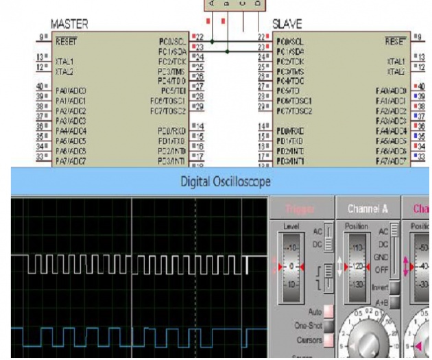
Simulation: