Completed AC after "Assumbly"
Air Filter Cover
AC Air Filter Cover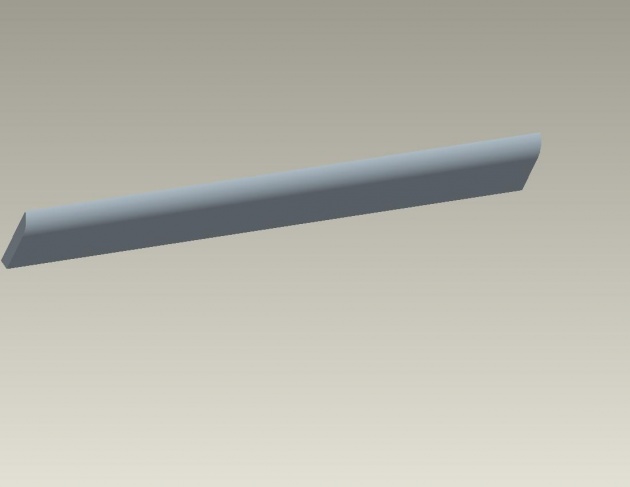
a)- I opened the new part for modeling the air filter cover and I selected the “front datum” for drawing the cover.
b)- Then I made vertical and horizontal references by using the reference line and selected the “rectangle tool” from the board of the front window of pro engineer.
c)- I drew a rectangle of length and width equal of the lower side cut of the AC case and entered the value 2 for the depth.
d)- By using the circle tool from the “ board of the main window” I made two screw post on the both side edges of the cover for “assemble” with the “main component” i.e. AC Case.
Assembly
First of all I clicked on the “file” and then clicked on the “new” and selected the “assembly”.
Then I clicked on the “insert>component>assemble” and selected the “AC Case Cover” at first to make it “main component” and from the “dialog box” appeared I selected it “default”.
Then I again clicked on the “insert>component>assemble” and selected the “Fan wheel” or “Fan Blade” or almost Fan Impeller from my PC where I have saved.
After that I selected the inner part of screw post of the “fan wheel” and then I clicked on the top of the screw post of the “AC case” so that it was “mate” and then I selected the inner side of the screw post of the “fan wheel” and then I clicked on the outer side of the screw post of the “AC Case” thus our “assembly” successfully done for Fan wheel and “totally constrained”.
After all I then clicked again on “insert>component>assemble” and selected the “Front Net covet” and opened it in our “assembly”.
After opening the “net cover” I first selected its inner part of screw post and then I clicked on the top surface of the screw post of the “AC case” thus it was “partially constrained” and then I selected the inner sided region of the screw post and then I clicked on the outer sided region of the screw post of the “AC Cove” for “matting” and “aligned” the “net cover”. Thus I did it also.
Now here is the next turn for Air filter cover and I again clicked on the “insert>component>assembly” and selected the part “AC Air Filter Cover” and opened it.
After doing that I selected the outer most surface of the screw post made on the “filter cover” and then I clicked on the inner part of the screw post of the “AC case” so that it is “partially constrained”. Again I selected the outer sided reign of the screw post of the filter cover and then I clicked on the inner sided reign of screw post of the “AC cover” for “Filter cover”.
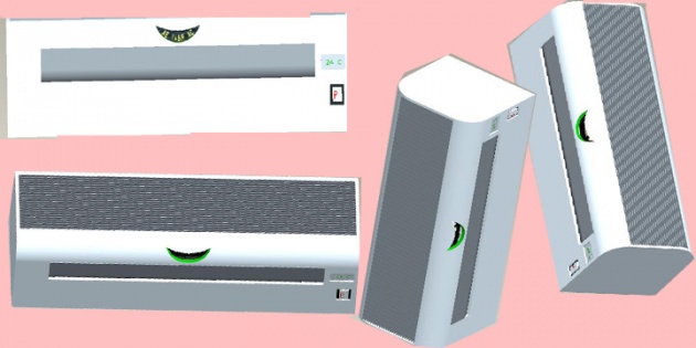
Thus “Filter cover” had “totally constrained” and Our “Assembly” has been successfully completed. And here in the top image, I have showed you different looks of my “Split Air Condition (AC)” which I designed by using “Pro-Engineer software”.
This is the last Article of the topic. (Thank you so much for reading my articles)
Writer: Amar Annex
Designer: Amar Annex
Contact email: engramr.yasir@gmail.com