- Second order filter often referred to as Biquads.
- Poles are complex conjugate in left half of the “s” plane and zeros are complex conjugate that may lie any where in ‘s’ plane.
7732_fa_rszd.jpg)
- It is to b remembered that:
T(s)=k(s+z1)/(s+p1)
Where K=b1/a0 , z1=b0/b1 (zero)
And p1=a0/a1 (pole)
In s plane these two quantities are located at s=-z1,s=-p1
- Pole,p1, will always lie on negative side of real axis
- Zero may be either positive or negative part of real axis
Design Parmeter “Q” and “Wo”:
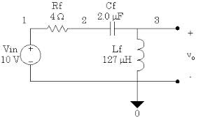
- We begin with PLC circyit shown in figure which has new familiar form of a voltage divider. The transfer function of given circuit will be:
T(S) =VL(s)/V1(s)
- The behaviourof the circuit at low frequency andhigh frequency is :
At low frequency, capacitoer behaves as open,then there is current in R, L and “c” circuit then
Vl=V1----approx equal
- At higher frequency, capacitor will act as short, so that Vl approaches the value Vl=0
7575_fa_rszd.jpg)
- From voltage divider :
T(s)= Z2/(Z1 + Z2)
This is the equation for second order circuit given above
T(s) = 1/cs/(R+Ls+1/cs) = 1/Ls/S(^2 + (R/L)s + 1/Lc)
- The result may be put into tandard form by defining new quantites, we observe that when defining new quantity then circuit is lossless with R=0 then
S^2 =1/Lc=0
- S1,S2=+-j1/Lc =+-jW
Mean poles are on imalnary axis and are conjugate axis.
- For lossy circuit or coils, for which a quality factor “Q” defined as Q/RLoss, which is the ratio of reactance at frequency “w” to resistance
At Frequency
w=w0
Q=WoL/R =1/R1/Lc
R/L=wo/Q
Put values of this equation in previous one, we get;
T(s) = wo^2/(s^2+ (wo/Q)s +Wo^2)
- The transfer function for low pass filter in this equation can be normalized form such that
T(j)=1
- Amore generalized form for T(s), in active circuit will recognize possibility of gain and also that, the associated circuit, may be inverting or no inverting
T(s)=+-Hwo^2/(s^2 + (wo/Q)s + wo^2
This can b represented as this diagram:
9294_fa_rszd.jpg)
- Now we scale frequency by dividing “s” by wo i.e., we use the normalized frequency, Sn=S/wo
- T(s)=+-H/(Swo)^2 + (1/Q)(S/wo+1)
=+-H/Sm^2+ (1/Q)(Sw0 +1)