Objectives:
To interface the serial port of PC with USART of AVR
To learn that how to program the USART (Universal Synchronous Asynchronous
Receiver / Transmitter) of AVR to transmit & receive asynchronously
Introduction:
USART of AVR has normal asynchronous, double-speed asynchronous, master synchronous
and slave synchronous mode features. Synchronous modes can be used to transfer data
between AVR and external peripherals such as ADC and EEPROMs etc. In this lab, we will
learn study and program the ATmega16 to transfer the data between AVR and PC using normal
asynchronous mode.
MAX232 – Level Converter IC
The serial port of computer sends/receives data serially at logic levels between -12 to +12V
whereas, microcontroller works at logic levels between 0 to 5V (TTL). So we need a RS-232 to
TTL and TTL to RS-232 converter and this is done by using RS-232 Level Converter IC,
MAX232 between PC and ATmega16.
Important Registers and Flags Associated with USART:
Following five registers are associated with the USART of AVR:
UDR: USART Data Register: Holds a byte which is received or to be transmitted via USART.
UCSRA: USART Control Status Register A: For controlling serial communication in AVR
UCSRB: USART Control Status Register B: For controlling serial communication in AVR
UCSRC: USART Control Status Register C: For controlling serial communication in AVR
UBRR: USART Baud Rate Register: Value written in this register determines the baud rate
Baud Rate Calculation:
Relationship between desired baud rate and the Fosc (crystal frequency) is given by:
Desired Baud Rate = Fosc
16(X+1)
Where X is the value loaded in the UBRR for a specific desired baud rate. Above
calculation will be true for default setting upon reset.
UCSRA(USART CONTROL AND STATUS REGISTER A)
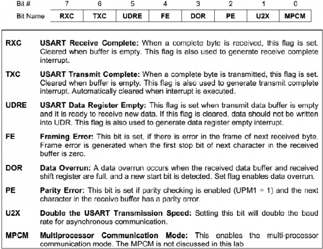
FE, PE and DOR are valid until UDR is read. Set these to zero for transmission
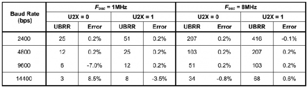
For crystal frequency of 1MHz and 8MHz, the most commonly used baud rates for
asynchronous operation can be generated by using the UBRR settings shown in the
following table:
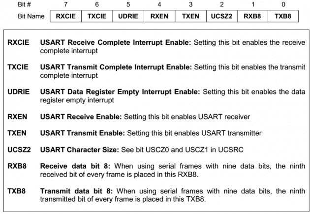
UCSRB(USART STATUS AND CONTROL REGISTER B):
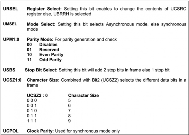
UCSRC(USART STATUS AND CONTROL REGISTER C):
Steps to Program the AVR to Transmit the Data Serially:
1. Enable the USART transmitter through UCSRB
2. Use 8 data bits, asynchronous mode, 1 stop bit and no parity through UCSRC
3. Calculate the value to be loaded in UBRR for a desired baud rate generation
4. Write the character into UDR which is to be transmitted serially
5. Monitor UDRE of TXC bits to check if character has been transmitted. You can
also enable interrupts associated with above flags to execute their respective
ISRs upon completion of transmission.
6. To transmit next character, go to step 4
Steps to Program the AVR to Receive the Data Serially:
1. Enable the USART receiver through UCSRB
2. Repeat steps 2 and 3 of transmit program
3. Monitor RXC bit to check if character has been received. You can also enable
interrupts associated with above flag to execute its respective ISR upon
reception of one complete character.
4. To transmit next character, go to step 3.
C Code for Serial Communication:
/*
This program receives a character from PC and transmit again to PC it after
incrementing. When transmission is complete, PortA is incremented to show that
transmission interrupt is executed
*/
#include<avr/io.h>
#include<avr/interrupt.h>
//Macros Definition
#define BitSet(p,m) ((p) |= (m))
#define BitClr(p, m) ((p) &= ~(m))
#define Bit(x) (0x01 << (x))
unsigned char x; //temporary variable, to hold the received character
int main(void)
{
DDRA = 0xFF; //PortA as output
UBRRL = 0x35; //0x35 = 53 ~ 53.0833 = (1000000/(16*1200))-1
BitSet(UCSRB, Bit(7)); //enable Receive Complete Interrupt
BitSet(UCSRB, Bit(6)); //enable Transmit Complete Interrupt
BitSet(UCSRB, Bit(4)); //enable Receiving
BitSet(UCSRB, Bit(3)); //enable Transmission
BitClr(UCSRB, Bit(2)); //enables 8 bit character size
BitSet(UCSRC, Bit(1)); //enables 8 bit character size
BitSet(UCSRC, Bit(2)); //enables 8 bit character size
BitSet(UCSRC, Bit(7)); //writes on UCSRC register if this bit is 1
//when clear, UBRRH value will be updated
sei(); //enable global interrupt
while(1); //stay here forever
}
//ISR for Receive interrupt
ISR (USART_RXC_vect)
{
x = UDR; //Store the received character into x
x++; //increment received character
UDR = x; //Transmit the incremented character
}
//ISR for Transmit interrupt
ISR (USART_TXC_vect) //This interrupt will trigger when transmission is complete
{
PORTA++; //increment PortA to show that transmit interrupt is executed
}