- Objectives:
To control the position of Servo Motor using variable PWM generated through AVR
Introduction:
Servo refers to an error sensing feedback control, which is used to correct the performance of a system. Servo Motors are DC motors equipped with a servo mechanism for precise control of angular position. The RC servo motors usually have a rotation limit from 0° to 180°. Some servos also have rotation limit of 360°. But servos do not rotate continuously. Their rotation is restricted in between the fixed angles.
A servo motor consists of several main parts, the motor and gearbox, a position sensor (potentiometer), PWM to voltage converter, error amplifier and motor driver. Following figure shows the block diagram of a typical servo motor.

PWM to Voltage Converter:
The PWM control input is feed to a PWM to voltage converter. This circuit charges a capacitor at a constant rate while the pulse is high. When the pulse goes low the charge on the capacitor is fed to the output via a suitable buffer amplifier. This produces a voltage related to the length of the applied pulse.
The circuit is tuned to produce a useful voltage over a 1ms to 2ms period. The output voltage is buffered and so does not decay significantly between control pulses.
Position Sensor (Potentiometer):
The current rotational position of the servo motor output shaft is read by a potentiometer which produces a voltage that is related to the absolute angle of the output shaft. The potentiometer then feeds its value into the Error Signal Amplifier which compares the current position with the required position from the PWM to voltage converter.
Error Signal Amplifier:
The error signal amplifier is an operational amplifier with negative feedback. It will always try to minimize the difference between the inverting and non-inverting inputs by driving its output in the correct direction. The output of the error amplifier is either a negative or positive voltage representing the difference between its inputs. Large error signal will produce higher output voltages from error signal amplifier.
The error amplifier output is used to drive the motor. If it is positive the motor will turn in one direction, otherwise in other direction. This allows the error amplifier to reduce the difference between its inputs (thus closing the negative feedback loop) and so make the servo go to the commanded position.
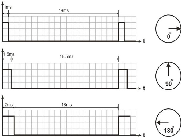
A typical value of the pulse width is somewhere in the range of 1.0 to 2.0ms. For a standard servo, a pulse width between 1.0ms to 2.0ms makes the servo to turn between 0 to 180.
However, these values could vary depending on the brand and make of the motor. A servo motor has three wires; two for supply voltages (Vcc and Ground) and third wire is used to supply the control PWM pulses.
Following figures show the different angle of rotation for the PWM of different duty cycles. Note that for 1ms duty cycle PWM, servo does not rotate and the maximum rotation i.e. 180 is achieved with the PWM having duty cycle of 10% (2ms).
C Code to control and position of servo motor using variable PWM :
/*
This programs generates the PWM of variable size to control the direction of a
servo motor having 0 to 180 rotation. Min. control pulse is 1ms and max. control
pulse is 2ms */
#include <avr/io.h>
#include <util/delay.h>
/*
CALCULATION:
We will use mode 14 (as per datasheet of ATmega16) to generate variab le top PWM
with ICR1. We need to calculate the top value for 50Hz PWM Freq
Formula:
Freq PWM = Freq cpu /N(1+Top) so
Top = (Freq CPU / (Freq PWM x N))-1
where N is prescaler
Freq CPU = 1MHz
Prescaler = 16
Freq PWM = 50Hz
Top = (1MHz / (50Hz x 8))-1
Top = 2499
Position of Servo Motor against different pulse widths
5% of 20ms = 1ms = 0 degree (min. rotation)
10% of 20ms = 2ms = 180 degrees (max. rotation)
5% Duty Cycle Calculation for non-inverting mode:
Duty Cycle (%) = ((OCR1x + 1) / Top + 1) * 100
5 / 100 = (OCR1x + 1) / (2499 + 1)
0.05 * 2500 = OCR1x + 1
OCR1x = 124
10% Duty Cycle Calculation for non-inverting mode:
Duty Cycle (%) = ((OCR1x + 1) / Top + 1) * 100
10 / 100 = (OCR1x + 1) / (2499 + 1)
0.1 * 2500 = OCR1x + 1
OCR1x = 249
*/
void main(void)
{
unsigned int x;
//Configure Timer1 registers
TCCR1A |= (1<<COM1A1)|(1<<WGM11); //Non-Inverted PWM
TCCR1B |= (1<<WGM13)|(1<<WGM12)|(1<<CS11); //Prescaler=16 Mode 14(Fast PWM)
ICR1 = 2499; //Freq PWM=50Hz, Time Period = 20ms
DDRD = 0xFF; //PWM generation on PortD5
while(1)
{
x = 124; //1ms = 5% of 20ms pulse
OCR1A = x; //0 degree rotation initially
_delay_ms(1000);
while(x <= 249) // continue till 2ms = 10% of 20ms Pulse
{
OCR1A=x;
_delay_ms(50);
x++;
}
}
}
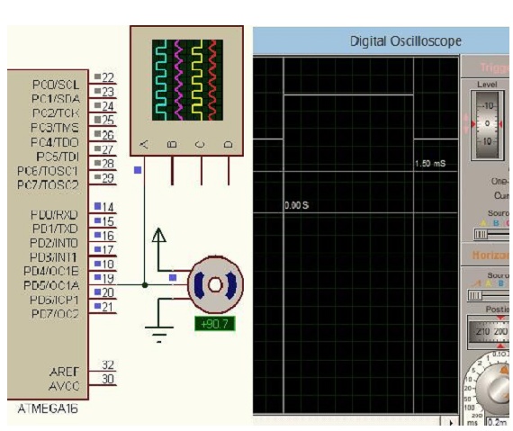
Simulation: