- Objectives:
- To understand the modes and functionality of timers of ATmega16
- To program Timer0 to generate a square waves
- To program Timer1 for event counting
Introduction:
Atmega16 has three timers. Timer 0 and Timer 2 are 8-bit timers whereas Timer 1 is the 16-bit
timer. Generally, a timer can be used in two modes i.e. Timer and Counter. If we use internal
clock source, then the frequency of the oscillator is fed to the timer. In this configuration, timer
can be used to generate the time delay. If we use the external clock, we insert pulses
through one of the I/O pins. In this configuration, timer can be used as event counter.
Important Registers and Flags Associated with Timers:
Each timer has following registers associated with it:
TCNTn: Timer/Counter Reg: Upon reset, it has zero value and counts up with each timer clock
TCCRn: Timer/Counter Control Reg: For setting modes of operation of Timer n
OCRn: Output Compare Reg: When contents of TCNT are equal to OCR, OCF flag is raised
and value of TCNTn is reset to zero
TOVn: Timer Overflow Flag: When overflow occurs, this flag is raised
OCFn: Output Compare Flag: Discussed in OCRn
There are four modes of operation. Each timer can be programmed to any one mode out of four
available modes options using timer mode selector bit i.e. WGM00 and WGM01 bits for timer0.
Following are the timer modes:
- Normal Mode:
In this mode, timer can be used for delay generation. Timer starts counting from the
initial value of TCNT0 up to the maximum value at every crystal clock (if no prescaler is
used). After the maximum value, TCNT0 register is reset to value 0x00. - CTC (Clear Timer on Capture match) Mode:
In CTC mode the counter is cleared to zero when the counter value (TCNT0) matches
the OCR0. The OCR0 defines the top value for the counter. - PWM, phase correct Mode
- Fast PWM Mode
a) TIMER 0 PROGRAMMING FOR SQUARE WAVE GENERATION:
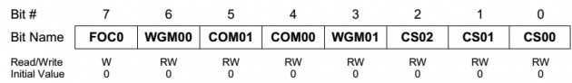
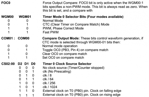
TCCR0(Timer/Counter Control Register)
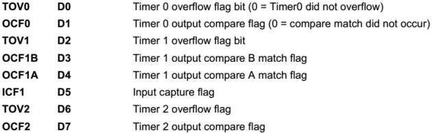
TIFR(Timer/Counter Interrupt Flag Register)
Steps to Program 8-Bit, Timer 0 in Normal Mode:
1. Load TCNT0 register with initial values from which the timer will count up.
2. Load TCCR0 register according to the operation required (Mode selection, pre scaler
setting etc.)
3. Keep monitoring TOV0 flag in TIFR register. If TOV0 flag is raised, timer overflow occurs.
Now clear TOV0 flag and proceed to step 1 again.
4.
Difference between Timer0 and Timer2:
1. Both the timers are 8-bit timers but first difference is that Timer2 can also be used as Real
Time Clock (RTC) when a crystal of 32.768 kHz is connected between TOSC1 and
TOSC2 pins and AS2 bit of ASSR (Asynchronous Status Reg.) is set.
2. Last two combinations of CS02-00 bits select the rising and falling edge of external event
counter in Timer0. Whereas in Timer2 these two combinations of CS22-20 bits used to
select different options of prescaler.
3. Timer2 cannot be used as an event counter.
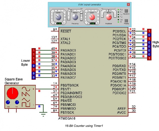
b) TIMER 1 PROGRAMMING FOR EVENT COUNTER:
Timer0 and timer1 can also be programmed to count the pulses or events (falling edge or rising
edge) T0 and T1 (PB0 and PB1) pins respectively.
Following steps are undertaken to program the timer1 as 16-bit event counter on T1. Before
programming Timer1, read all the registers of Timer1 thoroughly.
Steps to Program 16-Bit, Timer 1 as an event counter:
1. Activate pull-up on T1 (PB0) using C instruction PORTB = 0x01;
2. Load TCCR1A with 0x00 and TCCR1B register with value 0x06 (External clock source on
T1 pin. Clock on falling edge).
3. Now load TCNT1H and TCNT1L with 0x00 to initialize the 16-bit timer with the zero value.
4. Now whenever a falling edge will occur at T1, counter will be incremented.
//This program generates 5Hz square wave on PA0 with a duty cycle of 50%. ON time
// is 100ms and OFF time is also 100ms.
#include<avr/io.h>
#include<util/delay.h>
//Macros definition
#define BitGet(p,m) ((p) & (m))
#define BitSet(p,m) ((p) |= (m))
#define BitFlip(p,m) ((p) ^= (m))
#define Bit(x) (0x01 << (x))
void TimerDelay(void); //Function prototype declaration
void main(void)
{
DDRA = 0xFF; //Make PortA output
BitSet(PORTA, Bit(0)); //Initially set PA0
while(1)
{
BitFlip(PORTA, Bit(0)); //Toggle PA0
TimerDelay(); //Generates delay of about 100ms
}
}
/* delay calculation
For a clock generation of 5Hz (200ms), timer should be overflowed twice, so:
Timer overflow @ = 200ms / 2 = 100ms (0.1s high, 0.1s low)
Crystal Clock = 1MHz
Prescaler used = 1024
Timer clock = 1MHz / 1024 = 976.5625 Hz
Timer Period = 1/976.5625 = 1024us
Timer Value = 0.1s / 1024 x 10^-6 = 97.65625 = 98 (approx) */
void TimerDelay(void)
{
TCNT0 = 0x9F; // (256+1)-98 = 159 = 0x9F
TCCR0 = 0x05; //Timer0 ON, clk/1024 prescaler, Normal Mode
while(!BitGet(TIFR, Bit(0))); // Wait for timer0 overflow & TOV0 flag is raised
TCCR0 = 0x00; //Stop Timer
BitSet(TIFR, Bit(0)); //Clear TOV0
}
Simulation: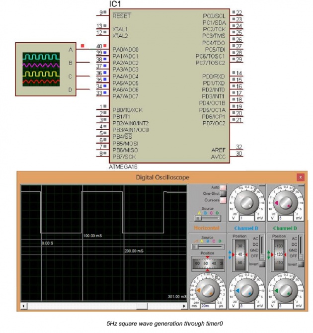
//This program counts the event occur at T1 (PB1) on every falling edge
//using 16-Bit Timer1 as event counter and shows the event count on PORTA and PORTC
//higher and lower byte respectively
#include<avr/io.h>
#include<util/delay.h>
//Start of main program
void main(void)
{
PORTB = 0x02; //Set a pull-up on PB2 (T1)
DDRA = 0xFF; //Make PORTA as output
DDRC = 0xFF; //Make PORTA as output
TCCR1A = 0x00; //Enable Counter Mode no falling adge at PB1
TCCR1B = 0x06;
while(1)
{
PORTC = TCNT1H; //Send higher byte of counter to PortC
PORTA = TCNT1L; //Send lower byte of counter to PortA
}
}
Simulation: