AIM OF THE EXPERIMENT
Uncontrolled rectification with R and RL load
Simulation Using MATLAB / Simulink
To check the performance parameter of uncontrolled full wave rectifier using R and RL loads
REQUIRED COMPONENTS AND EQUIPMENTS
1. Diodes
2. Resistive load(Resistance)
3. Inductor
4. RL load(Resistance + Inductor)
5. Oscilloscope
6. DMM.
THEORY
When AC -> DC voltages then there are losses in the circuits and thus
100% efficiency can't be achieved. It is important to get idea of efficiency to find in
systems losses beside this there are certain parameters which changes. Calculate its values using
the following formulae.
PERFORMANCE PARAMETERS
1. Wave form with only R load
2. Wave form with RL load
3. Average value of output voltage Vdc
4. Average value of output current Idc
5. Output dc power
Pdc=Vdc*Idc
6. Vrms
7. Irms
8. Vac= (V2rms - V2dc)1/2
9. The output ac power
Pac= Vrms*Irms
10. Efficiency η
η =
11. Form Factor FF
FF=
12. Ripple Factor RF
RF=
PROCEDURE
1. First of all draw the circuits of Fig.1, Fig.2, Fig.3 and Fig.4 in Simulink and simulate it. Do
also all analysis for comparison with hardware.
2. Construct the circuits as shown in Fig.1, Fig.2, Fig.3 and Fig.4 on breadboard.
3. First use Resistive load only and then completing the require results and taking
observations connect Resistive plus Inductive load (RL) and repeat the procedure again.
4. Note the reading as required to fill the table.
5. Make comparison between the results of rectifier with resistive load and resistive plus
inductive load.
6. Change the values of R and L if variable loads are available.
7. Make comparison due to variation of load.
8. Make comparison of the simulated and hardware values and graphs.
Fig.1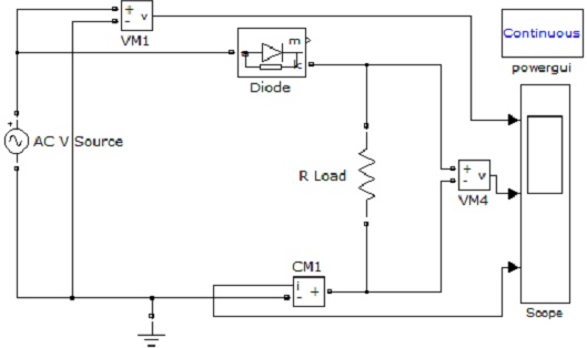
OBSERVATION:
Draw the wave form of the rectifier output with resistive load
Fill the following table(Performance parameter)
S.No Formulae Results
1 Vdc
2 Idc
3 Pdc
4 Vrms
5 Irms
6 Vac
7 Pac
8 η
9 FF
10 RF
Fig.2
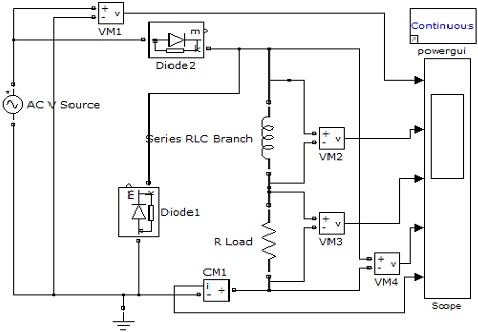
OBSERVATION:
Draw the wave form of the rectifier output with resistive load
Fill the following table(Performance parameter)
S.No Formulae Results
1 Vdc
2 Idc
3 Pdc
4 Vrms
5 Irms
6 Vac
7 Pac
8 η
9 FF
10 RF
CIRCUIT1
Note: The resistor R1 is power resistor. The Diodes are power diodes
Fig. 3
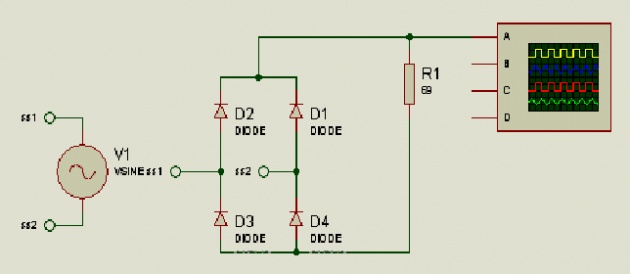
OBSERVATION:
Draw the wave form of the rectifier output with resistive load
Fill the following table(Performance parameter)
S.No Formulae Results
1 Vdc
2 Idc
3 Pdc
4 Vrms
5 Irms
6 Vac
7 Pac
8 η
9 FF
10 RF
CIRCUIT1
Note: The resistor R1 is power resistor. The Diodes are power diodes
Fig.4
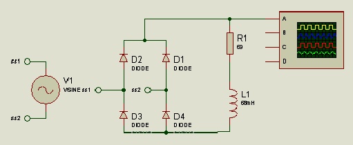
Observation:
Draw the wave form of the rectifier output with resistive load
Fill the following table (Performance parameter)
S.No Formulae
1 Vdc
2 Idc
3 Pdc
4 Vrms
5 Irms
6 Vac
7 Pac
8 η
9 FF
10 RF