AC Case
Round the Upper both Edges of the AC case:
a)- I first selected the upper top edge of ac case and then clicked the round tool in the board and set the value for the upper round is 1.00.
b)- Then I selected the upper lower edge and then clicked the round tool from the dash board and entered the value 0.7 in the box for the lower round.
Creating the first cut of AC Case:
a)- I Clicked Insert and then clicked on Extrude from the pro e window. Then opened Sketch plan from the board, and selected top surface of the first extrusion for drawing. Compliance with default settings and orientation of the window plan on which we sketch the object or part and agreed the sketcher and off the reference box.
b)- Then I selected the rectangular tool from the dash board and drew a new rectangle in the middle on the top surface of the ac case and set the horizontal valued 9.8 and vertical valued 2.00.
c)- Compliance with the features and entered 2.5 for the depth of the rectangle and then I selected the inward direction of the rectangle and clicked on the removed material icon dialog box and at least clicked on the check icon. Thus we have a first cut produced in our section.
Creating the Lower/side cut of AC Case:
a)- I clicked Insert and then clicked on Extrude and opened the window plane from the dashboard, and selected the lower/side of the AC case .
b)- Then I set the references using the reference line from the sketcher and selected the rectangle tool and draw the rectangle of week dimension on the side of the case.
c)- I entered the value 8 for horizontal of the lower cut and entered 0.88 for the vertical value and accepted the features.
d)- And I then clicked on the inward direction of the arrow of the rectangle and then clicked on the remove materials tool up to the next surface and then checked the icon. Thus we have a case modeled and ready which has been shown in above diagram.
Creating Screw Posts in the AC Case:
Using circle tool I created the screw posts for ‘front net cover’ , ‘fan wheel’ and for the ‘air filter’ cover using right dimensions according to parts as shown in above diagram.
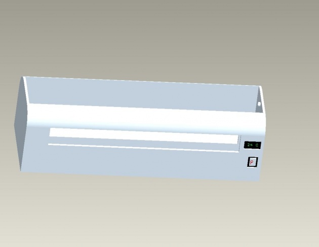
Addition of some Extra Features to AC Case:
I have added a power button, a trade mark sign on the front and small LCD screen for showing the output temperature in Centigrade (C) and receiving the remote signals directly as shown in the diagram given in part 2.
Writer: Amar Annex
Email: engramar.yasir@gmail.com