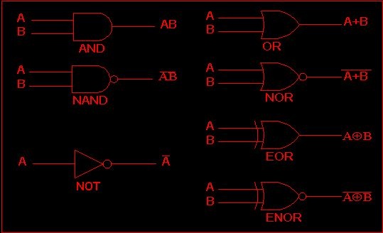
FUNDAMENTAL LOGIC GATES
Logic gates are electronic circuits in which transistors are used as high-sped switches.They implement various logic operations.They are used in calculators, digital watches, computers, robots and telecommunications and control systems etc. In these gates certain voltages levels simulate the two states such as 1 and 0. Ideally , one particular voltage level represents 1 (high). and another voltage level represents 0 (low).

In practical digital circuits, a state 1 or high can be any voltage between a specific minimum value and a specific maximum value. Likewise 0 can be any voltage level between a specific minimum vale and a specified maximum value. Logic gates are generally made in the form of an integrated circuits. Several gates can then be made in one pakege. Each gate will have one or more inputs and one output. A power supply is needed which is often 5V. The fundamental as well as a few of the derived gates will now be described.
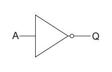

The not gate is the simplest of all logic gates as it has only one intput and only one output. It changes the input A so that a '1' input becomes a '0' output at Q and a '0' input becomes a '1' output, In electronics American standard symbols are commonly used as S. The action of logic gates is represented by means of a truth table. See the table in this figure. The function of a NOT gate is represented briefly by A bar Q or in words"not" A equals Q.