Objectives:
To learn the difference between polling and interrupt based programming
To use the timer interrupt
To use external hardware interrupt
Introduction:
There are two methods by which a microcontroller can serve a device
1- Interrupt: In interrupt method, a device sends an interrupt signal to microcontroller.
Upon reception of interrupt, microcontroller stops its working and serves the device.
Program executed after receiving an interrupt is called Interrupt Service Routine (ISR).
2- Polling: In polling, microcontroller continuously monitors the status of device, if the
status is met, microcontroller serves the device. In polling method, microcontroller can
only check single device at a time.
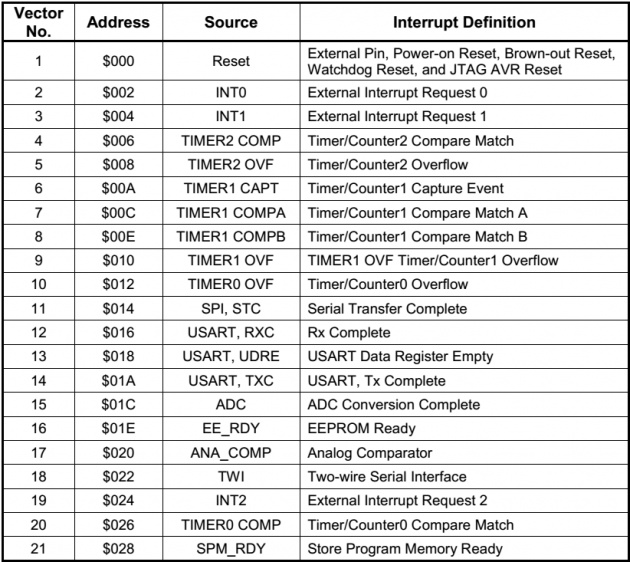
Above table shows the interrupt sources and their interrupt vectors for AVR ATmega16. Memory
locations from 0002 to 0028 locations are reserve for interrupt vectors. Each interrupt has 2
words (4 bytes) of memory space for its ISR. For example, 0012 to 0014 memory space is set
aside for Timer0 overflow ISR.
Usually ISR cannot fit into 4-bytes memory space. So a JMP instruction is kept at the vector
address from where ISR jumps to another location where rest of the code of ISR can be written.
At the end of each ISR, RETI (Return from Interrupt) instruction is placed which gives the
Steps to enable an Interrupt:
To enable any interrupt of AVR, we need to take the following steps:
1 Bit D7 (I) of SREG (Status Register) must be set in order to enable the global interrupt.
Without enabling global interrupt, no interrupt can happen. This can be done by using
SEI (assembly instruction) or sei(); (C instruction).
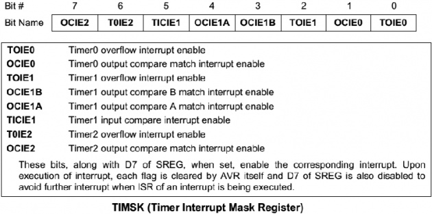
2 After enabling global interrupt, by setting the IE (Interrupt Enable) bit of each interrupt,
that specific interrupt can be enabled. For example, to enable Timer0 overflow interrupt,
we need to set TOIE0 (Bit0 of TIMSK Register).
When interrupt is executed, Bit D7 of SREG is cleared by the microcontroller to avoid the
occurrence of another interrupt. Moreover, if Timer0 overflow interrupt is enabled, TOV0
(Timer0 Overflow flag) is automatically cleared when microcontroller jumps to the Timer0
overflow interrupt vector table.
TIMER INTERRUPTS:
Timer Interrupt Mask Register (TIMSK) holds the different interrupt enable bits related to timers.
EXTERNAL HARDWARE INTERRUPTS:
There are three external hardware interrupts are INT0, INT1 and INT2 located on pins PD2,
PD3 and PB2 respectively.
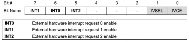
GICR(General Interrupt Control Register)
INT0 and INT1 can be programmed to trigger on low level, rising edge, falling edge or both
edges through MCUCR (MCU Control Register). Whereas, INT2 can only be programmed to
trigger on falling or rising edge through MCUCSR (MCU Control and Status Register).
If an interrupt is programmed for edge trigger mode, the pulse must be 1 instruction cycle to
ensure that the transition is seen by microcontroller. If an interrupt is programmed for level
trigger, the pin must be held low for at least 5 machine cycles to cause an interrupt.
control back to the location from where it was interrupted.