Objectives:
To interface the LCD and program AVR to show the characters on 2 x 16 LCD
Introduction:
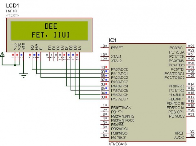
This lab demonstrated that an LCD can be interfaced in 4-bit mode to an ATmega16 AVR
microcontroller. LCD can also be used in 8-bit mode but the advantage of using it in 4-bit mode is that
we can save the I/O ports of a microcontroller. In 4-bit mode, we need to send the character after
splitting it into higher and lower nibbles (4-bits for data only).
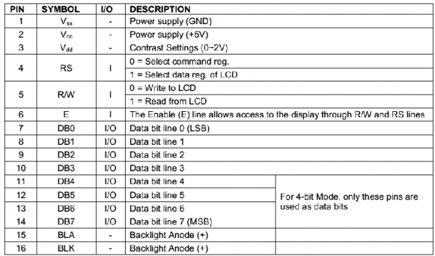
Supply Connections and Pins
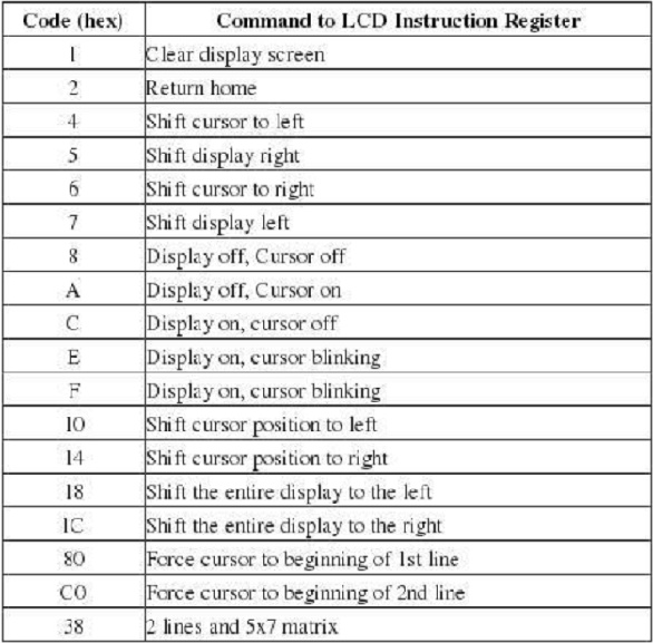
Following table shows some useful command list which is generally required to interface and program the microcontroller with LCD.
Steps to write on LCD:
To write the data or command on LCD, following steps are undertaken:
1. Set R/W bit to low
2. Set RS bit to logic 0 or 1 (command or character)
3. Set data to data lines (if it is writing)
4. Set E to high and then low for some time
5. Finally write the data from data lines (if it is reading)
// Program to interface LCD in 4 bit mode with AVR microcontroller
#include<avr/io.h>
#include<util/delay.h>
//Macros Definition
#define BitSet(p,m) ((p) |= (m))
#define BitClr(p, m) ((p) &= ~(m))
#define BitFlip(p,m) ((p) ^= (m))
#define Bit(x) (0x01 << (x))
void LCD_init();
void cmd_4b(unsigned char);
void data_4b(unsigned char);
void LCDcmd(unsigned char);
void LCDdata(unsigned char);
unsigned int main(void)
{
unsigned char data0[]="DEE";
unsigned char data1[]="FET, IIUI";
unsigned int i=0;
DDRA=0xFF;
LCD_init(); //Initialize LCD
cmd_4b(0x87); //Cursor at Line 1, Position 7
while(data0[i]!='\0') //continue loop until null is arrived
{
data_4b(data0[i]); //send all characters for 4-bit data conversion
_delay_ms(50);
i++; //to access next character of array
}
cmd_4b(0xC4); //Cursor at Line 2, Position 4
i=0;
while(data1[i]!='\0') //continue loop until null is arrived
{
data_4b(data1[i]); //send all characters for 4-bit data conversion
_delay_ms(50);
i++; //to access next character of array
}
while(1);
}
void LCD_init() // Initialize LCD
{
cmd_4b(0x02); //to initialize LCD in 4-bit mode.
cmd_4b(0x28); //to initialize LCD in 2 lines, 5x7 dots and 4bit mode
cmd_4b(0x0C); //Display is ON, cursor OFF
}
void cmd_4b(unsigned char Cmd)
{
char Cmd1;
Cmd1 = Cmd & 0xF0; //mask lower nibble because PA4-PA7 pins are used
LCDcmd(Cmd1); // send to LCD
Cmd = Cmd << 4; //shift left 4 bits
LCDcmd(Cmd1); // send to LCD
}
void data_4b(unsigned char data_value)
{
char data_value1;
data_value1 = data_value & 0xF0;
LCDdata(data_value1);
data_value1 = data_value << 4;
LCDdata(data_value1);
}
void LCDcmd(unsigned char cmdout)
{
PORTA = cmdout;
BitClr(PORTA, Bit(0)); //Clear RS
BitClr(PORTA, Bit(1)); //Clear RW
BitSet(PORTA, Bit(2)); //Set Enable
_delay_us(200);
BitClr(PORTA, Bit(2)); //Clear Enable
}
void LCDdata(unsigned char dataout)
{
PORTA = dataout;
BitSet(PORTA, Bit(0)); //Set RS
BitClr(PORTA, Bit(1)); //Clear RW
BitSet(PORTA, Bit(2)); //Set Enable
_delay_us(200);
BitClr(PORTA, Bit(2)); //Clear Enable
}
Simulation: