Objective :
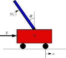
The objective of the control system is to balance the inverted pendulum by applying a force to the cart that the pendulum is attached to. It is unstable without control, so we learn how we can balance pendulum through control system.
Analysis :
We analyize our system by
1) Open loop impulse response
2) Open loop step response
Open loop Impulse Response :
We will examine how the system responds to an impulsive force applied to the cart, for this we use commands in matlab.and we examine that the system response is entirely unsatisfactory. In fact, it is not stable in open loop.
Open loop Step Response :
When we applied step input we examine that the response of the system is unstable. It is apparent from analysis above that some sort of control will need to designed to improve the response of the system.
PID Controller :
This closed-loop transfer function can be modeled in MATLAB, we make transfer function by the help of code. Specifically, we define our controller using the pid object in MATLAB. We then use the feedback command to generate the closed-loop transfer function T(S), where the disturbance force F is the input and the deviation of the pendulum angle from the vertical is the output.

Transfer Function :

Now we can begin to tune our controller. response of the closed-loop system to an impulse disturbance is still not stable. Let's begin to modify the response by increasing the proportional gain we get the response plot shown below

the steady-state error approaches zero in a sufficiently fast manner, no additional integral action is needed. we can set the integral gain constant to zero to see some integral control is needed. After some trial and error it is found that a derivative gain of 20 provides a satisfactory response.

As you can see, the overshoot has been reduced so that the pendulum does not move more than 0.05 radians away from the vertical. Since all of the given design requirements have been met, no further iteration is needed.
Whats happen to the cart's position :
The block representing the response of the cart's position was not included because that variable is not being controlled. It is interesting though, to see what is happening to the cart's position when the controller for the pendulum's angle is in place. To see this we need to consider the full system block diagram as shown in the following figure.

Adding the following commands to your m-file (presuming  and <img src="data:image/png;base64,iVBORw0KGgoAAAANSUhEUgAAAB0AAAAPCAYAAAAYjcSfAAADH0lEQVQ4EX1Vyyv8URQ/Mz/EwlhImmKFjPIqYSPJI2uSjRKRLBQSGxazGytk4R+gFEJICSnkbRazxELWipBH4fzO59S5vxmP36nv3Hs+533OvXeIo+jj4yOK+31reuvr67yysqKKn5+f3wwM6+jo4OfnZ6cXR0LCkcfjIa/XS+fn5zQ1NUV+v1/xgoICqqyspJmZGRoaGlIMek9PT3R9fU0tLS1wofa6+eGnrq6OmpubaWlpieLiJKRlg+w7Ozu5vb2dJbDLen5+ntPT01mMFHt/f9e1q6uLj4+PdW8+zAi8YdaV8fFxnpycVBVkrlReXs4QGMHIApSUlP


