Permanent Magnet Moving Coil Instrument
It’s deflection instrument uses a pointer that moves over a calibrated scale to indicate a measured quantity. For this to occur, three forces must operate inside the instrument.
Deflecting Force
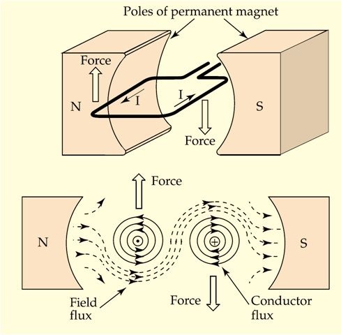
causes the pointer to move from its zero position when a current flows in the coil is magnetic force; the current in the coil sets up a magnetic field that interacts with the magnetic field of the permanent magnet
Controlling Force
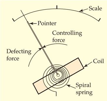
-is provided by spiral springs
-The springs retain the coil and pointer at their zero position when no current is flowing in the coil
- When current flows in the coil, the springs wind up as the coil rotates, and the force they exert on the coil increases
- The coil and pointer stop rotating when the controlling force becomes equal to the deflecting force
- The spring material must be nonmagnetic to avoid any magnetic field influence on the controlling force
Damping Force
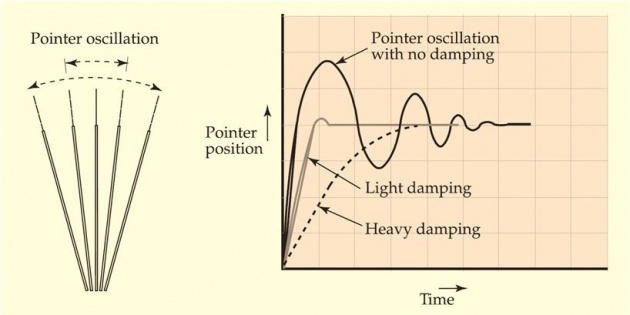
- is required to minimize (or damp out) the oscillations
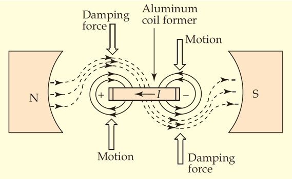
- In PMMC instruments, the damping force is normally provided by eddy currents.
- Eddy currents induced in the coil former (or frame) set up a magnetic flux that opposes the coil motion, thus damping the oscillations of the coil.
Two methods of supporting the moving system are
Jeweled Bearing Suspension
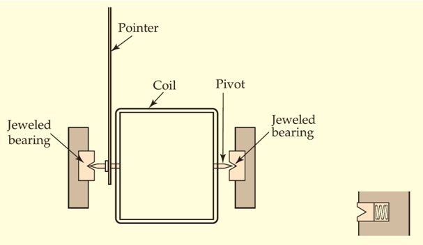
- The pointed ends of shafts or pivots fastened to the coil are inserted into cone-shaped cuts in jewel (sapphire or glass) bearings
- Least possible friction
- The bearings may be broken by the shock of an instrument being slammed down heavily upon a bench
- Some jewel bearings are spring supported to absorb such shocks more easily
- The most sensitive jeweled-bearing instruments give full scale deflection (FSD) with a coil current of 25 µA
Taut Band Method
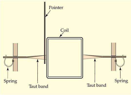
- Much tougher than jeweled-bearing suspension
- Two flat metal ribbons (phosphor bronze or platinum alloy) are held under tension by springs to support the coil
- Because of the springs, the metal ribbons behave like rubber under tension
- The ribbons also exert a controlling force as they twist, and they can be used as electrical connections to the moving coil
- With taut-band suspension FSD may be achieved with as little as 2 µA of coil current
PMMC Instrument Construction
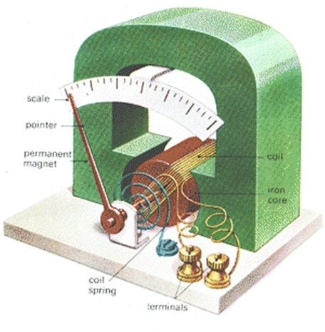
- The main feature is a permanent magnet with two soft-iron pole shoes
- A cylindrical soft-iron core is positioned between the shoes
- One of the two controlling spiral springs is shown. One end of this spring is fastened to the pivoted coil, and the other end is connected to an adjustable zero-position control
- Counterweights attached to the pointer for providing correct mechanical balance
- The current in the coil of a PMMC instrument must flow in one particular direction to cause the pointer to move (positively) from the zero position over the scale.
- The reversal of current causes the coil to rotate in the opposite direction, and the pointer is deflected to the left of zero (i.e., off-scale)
- The terminals of a PMMC instrument are identified as + and – to indicate the correct polarity for connection, and the instrument is said to be polarized
- Cannot be used directly to measure alternating current
- Without rectifiers, it is purely a dc instrument
Galvanometer
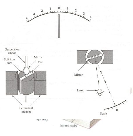
- Galvanometer is essentially a PMMC instrument designed to be sensitive to extremely low current levels
- Center-zero scale
- The scale may be calibrated in microamperes, or it may be a millimeter scale. In the latter case, the instrument current sensitivity is stated in
- Uses taut-band suspension
- Eddy current damping may be provided as in other PMMC instruments
- Sometimes a non-conducting coil frame is employed, and the damping current is generated by the moving coil. In this case, a damping resistor is connected in series with the coil, which controls the level of eddy current.
- Frequently, a critical damping resistance value is stated, which gives just sufficient damping to allow the pointer to settle down quickly.
- The light beam behaves as a very long weightless pointer which can be substantially deflected by a very small coil current
- Pointer galvanometers have current sensitivities ranging from 0.1 to 1 . For light-beam instruments typical current sensitivities are 0.01 to 0.1 per scale division.
- Voltage sensitivity is often expressed for a given value of critical damping resistance. This is usually stated in
- A megohm sensitivity is sometimes specified for galvanometers, and this is the value of resistance that must be connected in series with the instrument to restrict the deflection to one scale division when a potential difference of 1 V is applied across its terminals.
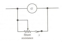
- Galvanometers are often employed to detect zero current or voltage in a circuit rather than to measure the actual level of current or voltage. In this situation, the instrument is referred to as a null detector. A galvanometer used as a null detector must be protected from the excessive current flow that might occur when the voltage across the instrument terminals is not close to zero. When the shunt resistance is zero, all of the circuit current flows through the shunt. As the shunt resistance is increased above zero, an increasing amount of current flows through the galvanometer
Source:
filmannex.com
bitlanders.com
uotechnology.edu.iq
utcc2.utcc.ac.th
filmannex.com