Hardware Description Language
A hardware description language is a computer language that is used to describe hardware.Currently, almost all integrated circuits are designed with using HDL.
Two HDLs are widely used
¡. Verilog HDL
¡. VHDL (Very High Speed Integrated Circuit Hardware Description Language)
Schematic design entry can be replaced by writing HDL code that CAD tools understand.
CAD tools can verify the HDL codes, and create the circuits automatically from HDL codes.
Facts About Verilog
We use Verilog, not VHDL for FPGA programming
¡ Verilog is more popular in industry than VHDL
¡ They offer similar features
History of Verilog
¡ In 1980s, originally developed by Gateway Design Automation.
¡ In 1990, was put in public domain.
¡ In 1995, adopted as an IEEE standard 1364-1995
¡ In 2001, an enhanced version, Verilog 2001
Functions of Verilog
¡ Design entry, like schematic
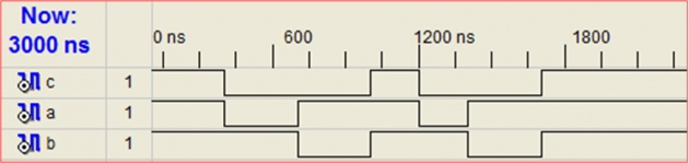
¡ Simulation and verification of your design
¡ Synthesis
Verilog Usage
Verilog may be used to model circuits and behaviors at various levels of abstraction:
¡ Transistor/Switch Level Modeling. LOW LEVEL
¡ Gate Level Modeling.
¡ Data Flow Modeling. HIGH LEVEL
¡ Behavioral or algorithmic Modeling.
For design with FPGA devices, transistor and gate level modeling is not appropriate.
Register Transfer Level (RTL) is a combination of behavioral and dataflow Modeling.
A Simple Verilog Example
// A simple example
module gate1 (a,b,c);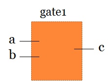
input a,b;
output c;
and (c,a,b);
endmodule
Modules are the basic building blocks in Verilog.
¡ A logic circuit à module, Its ports: inputs and outputs
¡ Begins with module, ends with endmodule
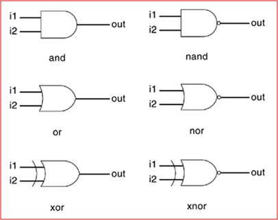
Basic Gates
Verilog supports basic logic gates as predefined primitives.
There are two classes of basic gates: and/or gates and buf/not gates.
And/or gates have one scalar output and multiple scalar inputs
The first terminal in the list of gate terminals is an output and the other terminals are inputs.
Example : Gate Instantiation of And/Or Gates
wire OUT, IN1, IN2;
and a1(OUT, IN1, IN2);
xnor (OUT, IN1, IN2);
// More than two inputs;
// 3 input nand gate
nand (OUT, IN1, IN2, IN3);