Part 1: Thyristor (SCR)
Aim of the experiment
1. To study the basic properties of the Thyristor.
2. To study and plot the conducting characteristics of the thyristor.
3. Designing of triggering circuit of thyristor
Required components and equipment
1. Thyristor BT151
2. Resistors
3. Potentiometers or Variable resistors
4. Oscilloscope
5. DMM.
Theory
Thyristor is one of most important semiconductor power devices which is used from very long time in power sector. It is of relatively high rating as compare to transistor. Although transistors replacedit at different places but still it is very common in power sector.
The SCR has three terminals, the cathode, anode and gate, as shown in the following Fig.1
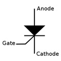
Fig.1
The SCR is a unidirectional device, which means it will pass electron current in one direction, from the cathode to anode. The SCR fires on (start conduction) when two conditions exist:
1. When it is forward biased, which occurs when the anode is more positive (+) than cathode.
2. When a positive voltage pulse is applied to the gate.
Once fired (SCR turned ON), the SCR will remain on if there is enough anode current (more than holding current) flowing through the anode to cathode, even when the positive gate voltage pulse terminate. This minimum anode current which keeps the SCR ON is called holding current. As shown in the following Fig.2
Note: Current is conventional current.

Fig.2
Note: The SCR will not fire on when cathode voltage is more positive than anode voltage, evenin the presence of gate voltage. As shown in fig.3

Fig.3
instead of above some key points that one should keep it in mind to perform experiment of SCR.
1. The requiredgate current Ig to turn on the SCR is dependent on VAK
i. More Ig require if VAK is smaller.
ii. Less Ig require if VAK is larger.
2. The IAK depends on Igonly to get SCR ON and then SCR remains ON. Thus IAK give information of the SCR that it will remain on or it will turn off after the removal of Ig.
Procedure:
1. Construct the circuits as shown in Fig.4
2. Use the fix resistive load at anode and a fixresistor at gate and connect a variable voltage source at VAK and Vg
3. With changing of VAK note the reading of Ig.
4. Repeat the step 3 to fill the table 1. Given below
5. For each value of VAK and Ig of step 3 and step 4 carefully note down the latch current IL and holding current IH.
6. An alternate solution isto Change the values of Rg and RL if variable loads are availableor variable supplies are not available which an alternate solution is.
Circuit1:
Note: The resistive load is any power resistor. The SCR is BT151
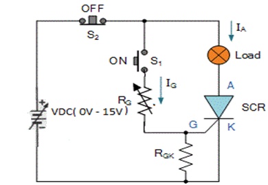
Fig. 4
Observation:
S.No VAK Vg Ig(Threshold) IL IH ID
Table 1.
Draw the Characteristic curve of SCR BT151. Using data of table 1
Conclusions:
Part 2: Triac
Aim of the experiment
1. To study the basic properties of the Triac.
2. To study and plot the conducting characteristics of the Triac.
3. Designing of triggering circuit of Triac.
Required components and equipments
1. Triac
2. Resistors
3. Potentiometers or Variable resistors
4. Oscilloscope
5. DMM.
Theory
Traic is also very important semiconductor power device. It is usually used to control AC voltages and thus very frequently uses in AC voltage regulators.
There basic theory of Thyristor and Triac is almost same the only difference is that there are to thyristors in Triac connected in opposite direction with common gate pin.
A triac has three terminals called MT1(main terminal1), MT2(main terminal2), and G(gate). The triac is bidirectional device, which means it passes current in anti-directions, through Module1 and Module2.
Triac turns ON when a voltage of at least 1 volt (depends datasheet ) of either polarity exist across MT1 and MT2 , and either a small positive or a small negative voltage is applied to gate.
Once turned on, the triac will remain on if there is enough current that passes through it btw Module1 and Module2. This is holding current. The triac continues to remain on even when the voltage applied to the gate is removed.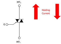
Fig.6
Procedure
1. Construct the circuits as shown in Fig.7
2. Use the fix resistive load (Power resistor) at anode and a fix resistor at gate and connect a variable voltage source at VDc and Vg
3. With changing of VDC note the reading of Ig.
4. Repeat the step 3 to fill the table 1. Given below
5. For each value of Vdc and Ig of step 3 and step 4 carefully note down the latch current IL and holding current IH.
6. Change the values of Rg and RL if variable loads are available which an alternate solution is.
Circuit2
Note: The resistive load is lighting bulb. The SCR is BT151

Fig.7
Observation:
S.No VAK Vg Ig(Threshold) IL IH ID
Table 2.
Procedure
1. Construct the circuits as shown in Fig.8
2. Use the fix resistive load at anode and a fix resistor at gate and connect a variable voltage source at VDc and Vg
3. With changing of VDC note the reading of Ig.
4. Repeat the step 3 to fill the table 1. Given below
5. For each value of Vdc and Ig of step 3 and step 4 carefully note down the latch current IL and holding current IH.
6. Change the values of Rg and RL if variable loads are available whichalternate solution is.
Circuit3
Note: There is only difference of polarity of VDC of fig.7 and fig.8
Note: The resistive load is lighting bulb. The SCR is BT151
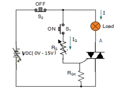
Fig.8
Observation:
S.No VAK Vg Ig(Threshold) IL IH ID
Table 3.
Draw the Characteristic curve of SCR BT151. Using data of table 2 & table 3.